LaTeX TikZ Colorful Background Layer
pgfonlayer environment
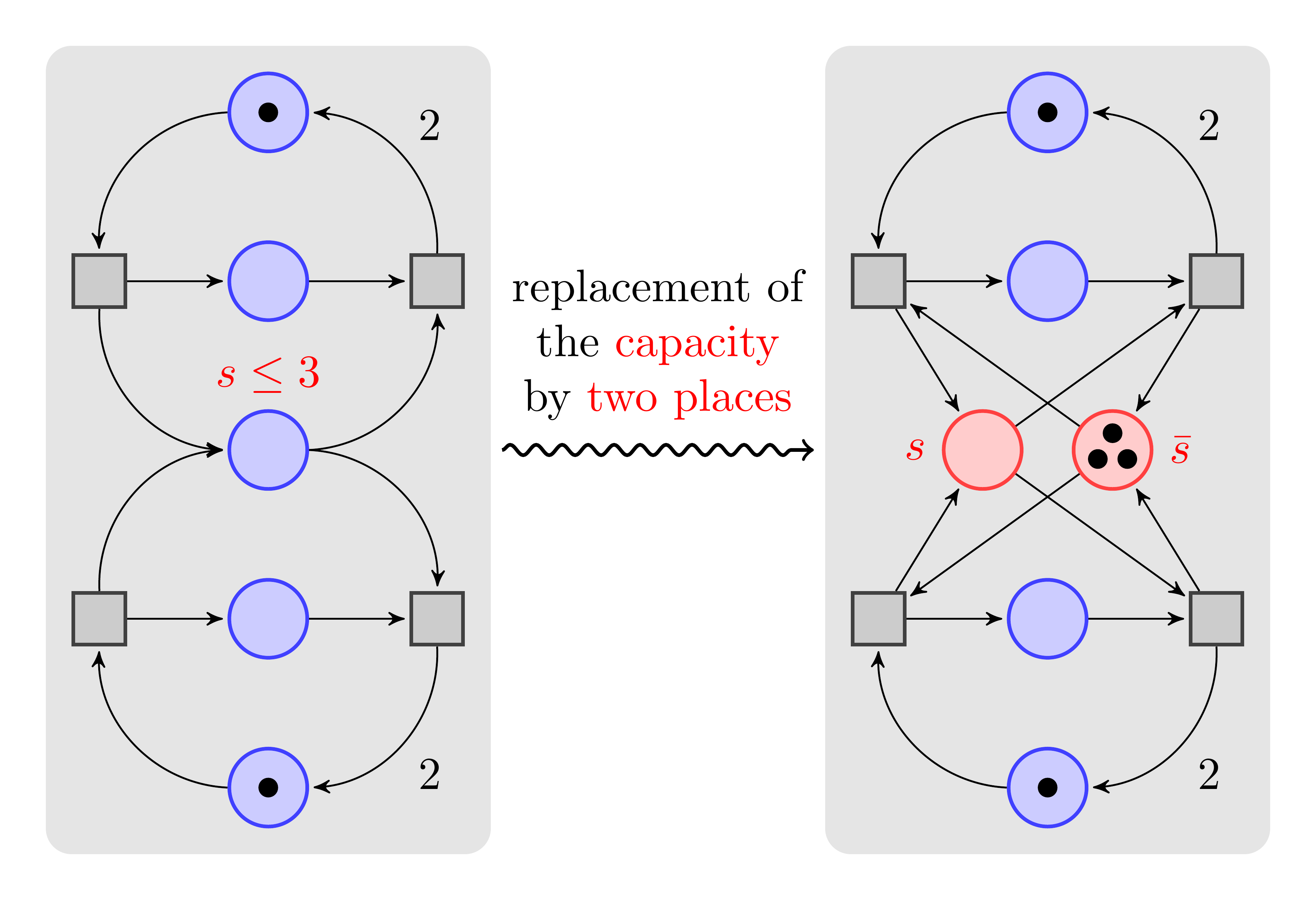
There’s an example, A Petri-net for Hagen, on TeXample.net1 and TikZ & PGF Manual2:
1
2
3
4
5
6
7
8
9
10
11
12
13
14
15
16
17
18
19
20
21
22
23
24
25
26
27
28
29
30
31
32
33
34
35
36
37
38
39
40
41
42
43
44
45
46
47
48
49
50
51
52
53
54
55
56
57
58
59
60
61
62
63
64
65
66
67
68
69
70
71
72
73
74
75
76
77
78
79
80
81
82
83
84
85
86
87
88
89
90
91
92
93
94
95
96
97
98
99
100
101
102
103
% Author: Till Tantau
% Source: The PGF/TikZ manual
\documentclass{standalone}
\standaloneconfig{border=1em}

\def\xcolorversion{2.00}
\def\xkeyvalversion{1.8}

\usepackage[version=0.96]{pgf}
\usepackage{tikz}
\usetikzlibrary{arrows,shapes,snakes,automata,backgrounds,petri}
\usepackage[latin1]{inputenc}
\begin{document}

\begin{tikzpicture}[node distance=1.3cm,>=stealth',bend angle=45,auto]
  \tikzstyle{place}=[circle,thick,draw=blue!75,fill=blue!20,minimum size=6mm]
  \tikzstyle{red place}=[place,draw=red!75,fill=red!20]
  \tikzstyle{transition}=[rectangle,thick,draw=black!75,
  			  fill=black!20,minimum size=4mm]

  \tikzstyle{every label}=[red]

  \begin{scope}
    % First net
    \node [place,tokens=1] (w1)                                    {};
    \node [place] (c1) [below of=w1]                      {};
    \node [place] (s)  [below of=c1,label=above:$s\le 3$] {};
    \node [place] (c2) [below of=s]                       {};
    \node [place,tokens=1] (w2) [below of=c2]                      {};

    \node [transition] (e1) [left of=c1] {}
      edge [pre,bend left]                  (w1)
      edge [post,bend right]                (s)
      edge [post]                           (c1);

    \node [transition] (e2) [left of=c2] {}
      edge [pre,bend right]                 (w2)
      edge [post,bend left]                 (s)
      edge [post]                           (c2);

    \node [transition] (l1) [right of=c1] {}
      edge [pre]                            (c1)
      edge [pre,bend left]                  (s)
      edge [post,bend right] node[swap] {2} (w1);

    \node [transition] (l2) [right of=c2] {}
      edge [pre]                            (c2)
      edge [pre,bend right]                 (s)
      edge [post,bend left]  node {2}       (w2);
  \end{scope}

  \begin{scope}[xshift=6cm]
    % Second net
    \node [place,tokens=1]
                      (w1')                                                {};
    \node [place]     (c1') [below of=w1']                                 {};
    \node [red place] (s1') [below of=c1',xshift=-5mm,label=left:$s$]      {};
    \node [red place,tokens=3]
                      (s2') [below of=c1',xshift=5mm,label=right:$\bar s$] {};
    \node [place]     (c2') [below of=s1',xshift=5mm]                      {};
    \node [place,tokens=1]
                      (w2') [below of=c2']                                 {};

    \node [transition] (e1') [left of=c1'] {}
      edge [pre,bend left]                  (w1')
      edge [post]                           (s1')
      edge [pre]                            (s2')
      edge [post]                           (c1');

    \node [transition] (e2') [left of=c2'] {}
      edge [pre,bend right]                 (w2')
      edge [post]                           (s1')
      edge [pre]                            (s2')
      edge [post]                           (c2');

    \node [transition] (l1') [right of=c1'] {}
      edge [pre]                            (c1')
      edge [pre]                            (s1')
      edge [post]                           (s2')
      edge [post,bend right] node[swap] {2} (w1');

    \node [transition] (l2') [right of=c2'] {}
      edge [pre]                            (c2')
      edge [pre]                            (s1')
      edge [post]                           (s2')
      edge [post,bend left]  node {2}       (w2');
  \end{scope}

  \draw [-to,thick,snake=snake,segment amplitude=.4mm,
         segment length=2mm,line after snake=1mm]
    ([xshift=5mm]s -| l1) -- ([xshift=-5mm]s1' -| e1')
    node [above=1mm,midway,text width=3cm,text centered]
      {replacement of the \textcolor{red}{capacity} by
        \textcolor{red}{two places}};

  \begin{pgfonlayer}{background}
    \filldraw [line width=4mm,join=round,black!10]
      (w1.north  -| l1.east)  rectangle (w2.south  -| e1.west)
      (w1'.north -| l1'.east) rectangle (w2'.south -| e1'.west);
  \end{pgfonlayer}
\end{tikzpicture}

\end{document}
In this example, two parts of graphs are respectively put in two scope environments in tikzpicture.
scope environment3
1
2
3
\begin{scope}<animations spec>[<options>]
	<environment contents>
\end{scope}
All <options> are local to the <environment contents>. Furthermore, the clipping path is also local to the environment, that is, any clipping done inside the environment “ends” at its end.
Then, two gray backgrounds are created and put underneath above two graphs by following code:
1
2
3
4
5
\begin{pgfonlayer}{background}
    \filldraw [line width=4mm,join=round,black!10]
    (w1.north  -| l1.east)  rectangle (w2.south  -| e1.west)
    (w1'.north -| l1'.east) rectangle (w2'.south -| e1'.west);
\end{pgfonlayer}
Actually, these two backgrounds are two blank but gray layers created by pgfonlayer environment:
113.3 Using Layers4
Once the layers of your picture have been declared, you can start to “fill” them. As said before, all graphics commands are normally added to the main layer. Using the {pgfonlayer} environment, you can tell pgf that certain commands should, instead, be added to the given layer.
1
2
3
\begin{pgfonlayer}{<layer name>}
	<environment contents>
\end{pgfonlayer}
The whole <environment contents> is added to the layer with the name <layer name>. This environment can be used anywhere inside a picture. Thus, even if it is used inside a {pgfscope} or a TeX group, the contents will still be added to the “whole” picture. Using this environment multiple times inside the same picture will cause the <environment contents> to accumulate.
Note: You can not add anything to the main layer using this environment. The only way to add anything to the main layer is to give graphic commands outside all {pgfonlayer} environments.
\filldraw5: Inside {tikzpicture} this is an abbreviation for \path[fill,draw].
The use of -| is artful, and relevant information can be found in6.
By the way, TikZ library backgrounds is needed:
1
\usetikzlibrary{...,backgrounds,...}
\tikzset command
If we want to specify a background for the whole tikzpicture, referring to documentation7 , we can use \tikzset command to set a background rectangle (15th line in the following code), and add the framed option (that is a shorthand for show background rectangle.8) to tikzpicture environment (16th line). TikZ library backgrounds is also necessary in this case.
1
2
3
4
5
6
7
8
9
10
11
12
13
14
15
16
17
18
19
20
21
22
23
24
25
26
27
28
29
30
31
32
33
34
35
36
37
38
39
40
41
42
43
44
45
46
47
48
49
50
51
52
53
54
55
56
57
58
59
60
61
62
63
64
65
66
67
68
69
70
71
72
73
74
75
76
77
78
79
80
81
82
83
84
85
86
87
88
89
90
91
92
93
94
95
96
97
98
99
100
101
102
103
104
% Author: Till Tantau
% Source: The PGF/TikZ manual
\documentclass{standalone}
\standaloneconfig{border=1em}

\def\xcolorversion{2.00}
\def\xkeyvalversion{1.8}

\usepackage[version=0.96]{pgf}
\usepackage{tikz}
\usetikzlibrary{arrows,shapes,snakes,automata,backgrounds,petri}
\usepackage[latin1]{inputenc}
\begin{document}

\tikzset{background rectangle/.style={rounded corners,fill=blue!20}}
\begin{tikzpicture}[framed,node distance=1.3cm,>=stealth',bend angle=45,auto]
  \tikzstyle{place}=[circle,thick,draw=blue!75,fill=blue!20,minimum size=6mm]
  \tikzstyle{red place}=[place,draw=red!75,fill=red!20]
  \tikzstyle{transition}=[rectangle,thick,draw=black!75,
  			  fill=black!20,minimum size=4mm]

  \tikzstyle{every label}=[red]

  \begin{scope}
    % First net
    \node [place,tokens=1] (w1)                                    {};
    \node [place] (c1) [below of=w1]                      {};
    \node [place] (s)  [below of=c1,label=above:$s\le 3$] {};
    \node [place] (c2) [below of=s]                       {};
    \node [place,tokens=1] (w2) [below of=c2]                      {};

    \node [transition] (e1) [left of=c1] {}
      edge [pre,bend left]                  (w1)
      edge [post,bend right]                (s)
      edge [post]                           (c1);

    \node [transition] (e2) [left of=c2] {}
      edge [pre,bend right]                 (w2)
      edge [post,bend left]                 (s)
      edge [post]                           (c2);

    \node [transition] (l1) [right of=c1] {}
      edge [pre]                            (c1)
      edge [pre,bend left]                  (s)
      edge [post,bend right] node[swap] {2} (w1);

    \node [transition] (l2) [right of=c2] {}
      edge [pre]                            (c2)
      edge [pre,bend right]                 (s)
      edge [post,bend left]  node {2}       (w2);
  \end{scope}

  \begin{scope}[xshift=6cm]
    % Second net
    \node [place,tokens=1]
                      (w1')                                                {};
    \node [place]     (c1') [below of=w1']                                 {};
    \node [red place] (s1') [below of=c1',xshift=-5mm,label=left:$s$]      {};
    \node [red place,tokens=3]
                      (s2') [below of=c1',xshift=5mm,label=right:$\bar s$] {};
    \node [place]     (c2') [below of=s1',xshift=5mm]                      {};
    \node [place,tokens=1]
                      (w2') [below of=c2']                                 {};

    \node [transition] (e1') [left of=c1'] {}
      edge [pre,bend left]                  (w1')
      edge [post]                           (s1')
      edge [pre]                            (s2')
      edge [post]                           (c1');

    \node [transition] (e2') [left of=c2'] {}
      edge [pre,bend right]                 (w2')
      edge [post]                           (s1')
      edge [pre]                            (s2')
      edge [post]                           (c2');

    \node [transition] (l1') [right of=c1'] {}
      edge [pre]                            (c1')
      edge [pre]                            (s1')
      edge [post]                           (s2')
      edge [post,bend right] node[swap] {2} (w1');

    \node [transition] (l2') [right of=c2'] {}
      edge [pre]                            (c2')
      edge [pre]                            (s1')
      edge [post]                           (s2')
      edge [post,bend left]  node {2}       (w2');
  \end{scope}

  \draw [-to,thick,snake=snake,segment amplitude=.4mm,
         segment length=2mm,line after snake=1mm]
    ([xshift=5mm]s -| l1) -- ([xshift=-5mm]s1' -| e1')
    node [above=1mm,midway,text width=3cm,text centered]
      {replacement of the \textcolor{red}{capacity} by
        \textcolor{red}{two places}};

  \begin{pgfonlayer}{background}
    \filldraw [line width=4mm,join=round,black!10]
      (w1.north  -| l1.east)  rectangle (w2.south  -| e1.west)
      (w1'.north -| l1'.east) rectangle (w2'.south -| e1'.west);
  \end{pgfonlayer}
\end{tikzpicture}

\end{document}
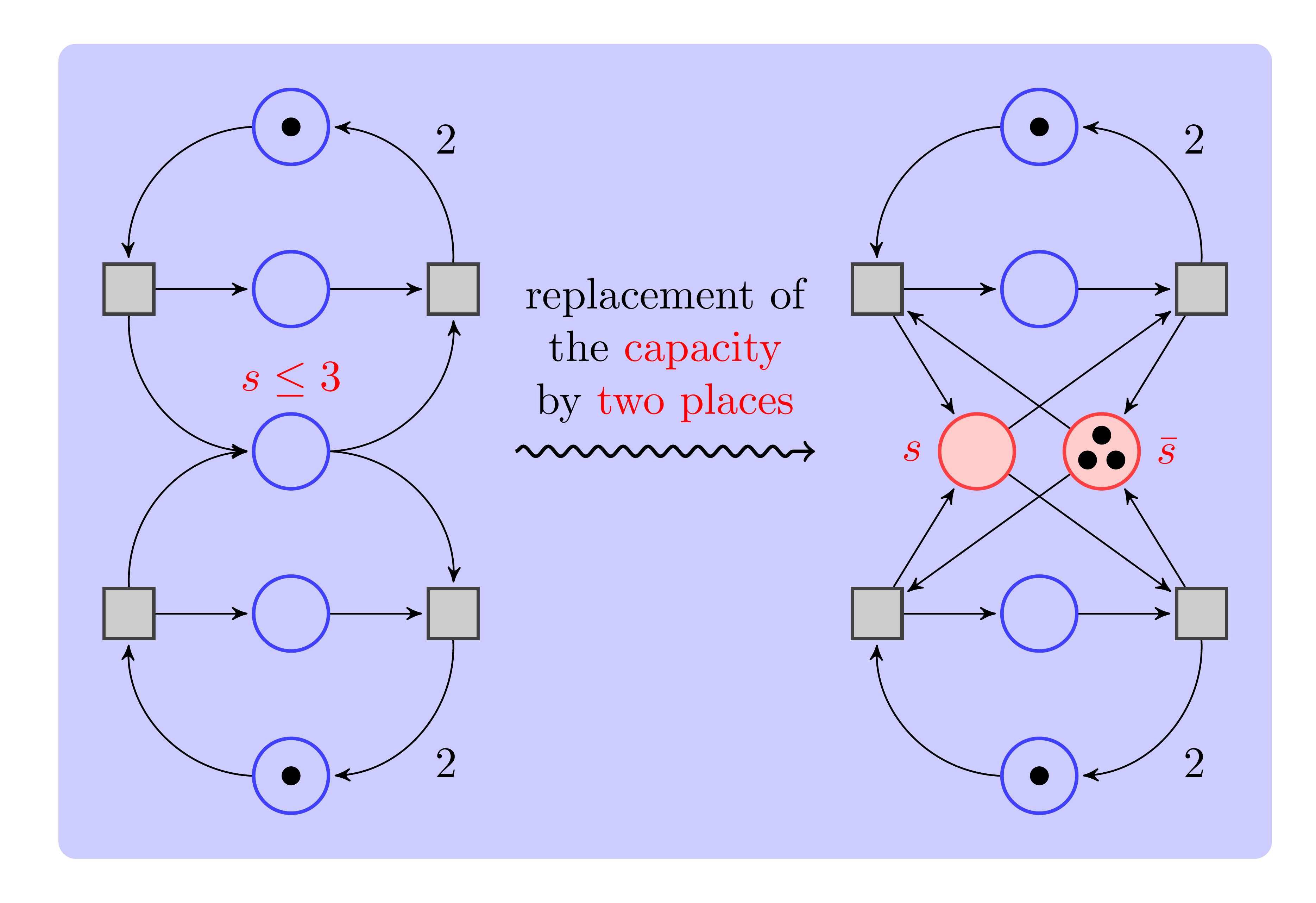
However, as can be seen, the newly added background lays on the middle of main layer and background layer, covering the latter. We can specify opacity of the background rectangle to mitigate it, for example:
1
\tikzset{background rectangle/.style={rounded corners,fill=blue!20,opacity=0.2}}
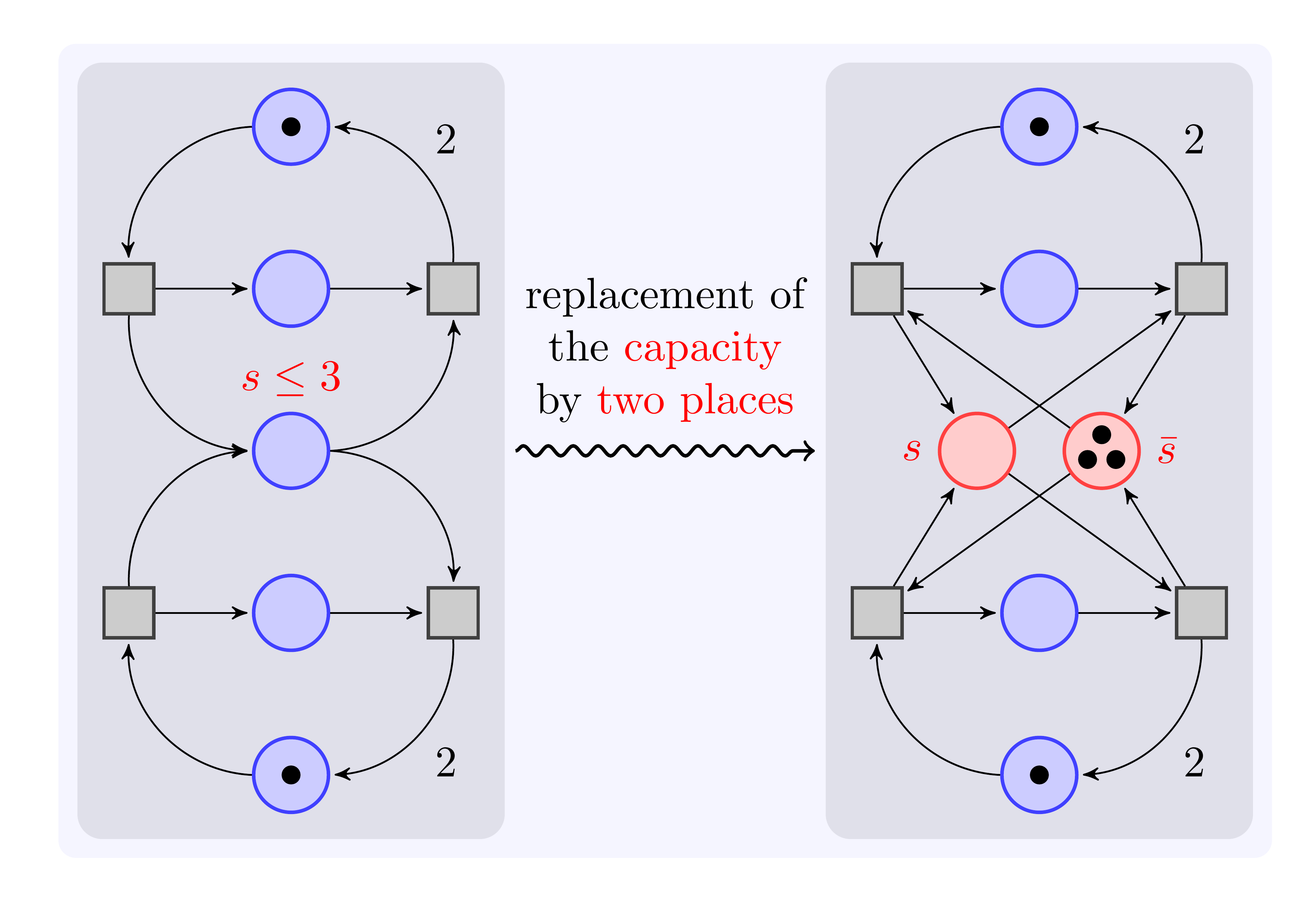
We can see the background layer at this time. However, what I exactly want is to make background rectangle be the bottom layer, but I don’t find a way to change layers order in this case.
Specify layers order
To change layers order (refer to4), we can also use pgfonlayer environment to create a whole background (see 102-111th line in the following code), and declare layers name and specify whose order before tikzpicture environment (17th-19th line). The complete code for realization shows as follows:
1
2
3
4
5
6
7
8
9
10
11
12
13
14
15
16
17
18
19
20
21
22
23
24
25
26
27
28
29
30
31
32
33
34
35
36
37
38
39
40
41
42
43
44
45
46
47
48
49
50
51
52
53
54
55
56
57
58
59
60
61
62
63
64
65
66
67
68
69
70
71
72
73
74
75
76
77
78
79
80
81
82
83
84
85
86
87
88
89
90
91
92
93
94
95
96
97
98
99
100
101
102
103
104
105
106
107
108
109
110
111
112
113
114
% Author: Till Tantau
% Source: The PGF/TikZ manual
\documentclass{standalone}
\standaloneconfig{border=1em}

\def\xcolorversion{2.00}
\def\xkeyvalversion{1.8}

\usepackage[version=0.96]{pgf}
\usepackage{tikz}
\usetikzlibrary{fit}

\usetikzlibrary{arrows,shapes,snakes,automata,backgrounds,petri}
\usepackage[latin1]{inputenc}
\begin{document}

\pgfdeclarelayer{bg1}
\pgfdeclarelayer{bg2}
\pgfsetlayers{bg2,bg1,main}

\begin{tikzpicture}[node distance=1.3cm,>=stealth',bend angle=45,auto]
  \tikzstyle{place}=[circle,thick,draw=blue!75,fill=blue!20,minimum size=6mm]
  \tikzstyle{red place}=[place,draw=red!75,fill=red!20]
  \tikzstyle{transition}=[rectangle,thick,draw=black!75,
  			  fill=black!20,minimum size=4mm]

  \tikzstyle{every label}=[red]

  \begin{scope}
    % First net
    \node [place,tokens=1] (w1)                                    {};
    \node [place] (c1) [below of=w1]                      {};
    \node [place] (s)  [below of=c1,label=above:$s\le 3$] {};
    \node [place] (c2) [below of=s]                       {};
    \node [place,tokens=1] (w2) [below of=c2]                      {};

    \node [transition] (e1) [left of=c1] {}
      edge [pre,bend left]                  (w1)
      edge [post,bend right]                (s)
      edge [post]                           (c1);

    \node [transition] (e2) [left of=c2] {}
      edge [pre,bend right]                 (w2)
      edge [post,bend left]                 (s)
      edge [post]                           (c2);

    \node [transition] (l1) [right of=c1] {}
      edge [pre]                            (c1)
      edge [pre,bend left]                  (s)
      edge [post,bend right] node[swap] {2} (w1);

    \node [transition] (l2) [right of=c2] {}
      edge [pre]                            (c2)
      edge [pre,bend right]                 (s)
      edge [post,bend left]  node {2}       (w2);
  \end{scope}

  \begin{scope}[xshift=6cm]
    % Second net
    \node [place,tokens=1]
                      (w1')                                                {};
    \node [place]     (c1') [below of=w1']                                 {};
    \node [red place] (s1') [below of=c1',xshift=-5mm,label=left:$s$]      {};
    \node [red place,tokens=3]
                      (s2') [below of=c1',xshift=5mm,label=right:$\bar s$] {};
    \node [place]     (c2') [below of=s1',xshift=5mm]                      {};
    \node [place,tokens=1]
                      (w2') [below of=c2']                                 {};

    \node [transition] (e1') [left of=c1'] {}
      edge [pre,bend left]                  (w1')
      edge [post]                           (s1')
      edge [pre]                            (s2')
      edge [post]                           (c1');

    \node [transition] (e2') [left of=c2'] {}
      edge [pre,bend right]                 (w2')
      edge [post]                           (s1')
      edge [pre]                            (s2')
      edge [post]                           (c2');

    \node [transition] (l1') [right of=c1'] {}
      edge [pre]                            (c1')
      edge [pre]                            (s1')
      edge [post]                           (s2')
      edge [post,bend right] node[swap] {2} (w1');

    \node [transition] (l2') [right of=c2'] {}
      edge [pre]                            (c2')
      edge [pre]                            (s1')
      edge [post]                           (s2')
      edge [post,bend left]  node {2}       (w2');
  \end{scope}

  \draw [-to,thick,snake=snake,segment amplitude=.4mm,
         segment length=2mm,line after snake=1mm]
    ([xshift=5mm]s -| l1) -- ([xshift=-5mm]s1' -| e1')
    node [above=1mm,midway,text width=3cm,text centered]
      {replacement of the \textcolor{red}{capacity} by
        \textcolor{red}{two places}};

  \begin{pgfonlayer}{bg1}
    \filldraw [line width=4mm,join=round,color=black!10]
      (w1.north  -| l1.east)  rectangle (w2.south  -| e1.west)
      (w1'.north -| l1'.east) rectangle (w2'.south -| e1'.west);
  \end{pgfonlayer}

  \begin{pgfonlayer}{bg2}
      \filldraw [line width=4mm,join=round,color=blue!20]
      (current bounding box.south west) rectangle (current bounding box.north east);
  \end{pgfonlayer}

\end{tikzpicture}
\end{document}
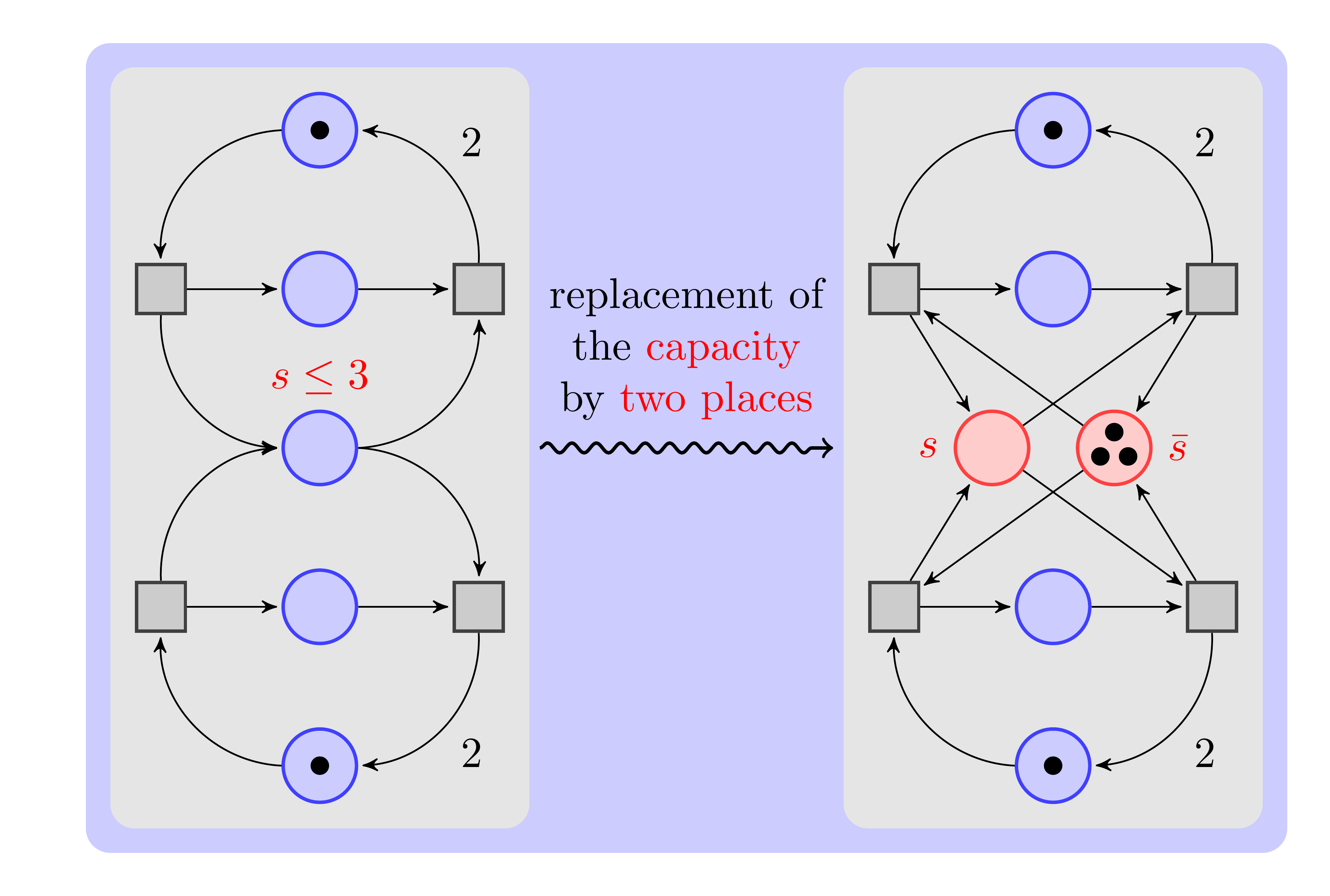
Which way is more elegant. One point should be particularly noted that how to use relative orientation of current bounding box to create a background spanning the whole tikzpicture:
1
2
3
4
\begin{pgfonlayer}{bg2}
    \filldraw [line width=4mm,join=round,color=blue!20]
    (current bounding box.south west) rectangle (current bounding box.north east);
\end{pgfonlayer}
References