LaTeX TikZ Commands -| and |-
14.2.2 Horizontal and Vertical Lines1
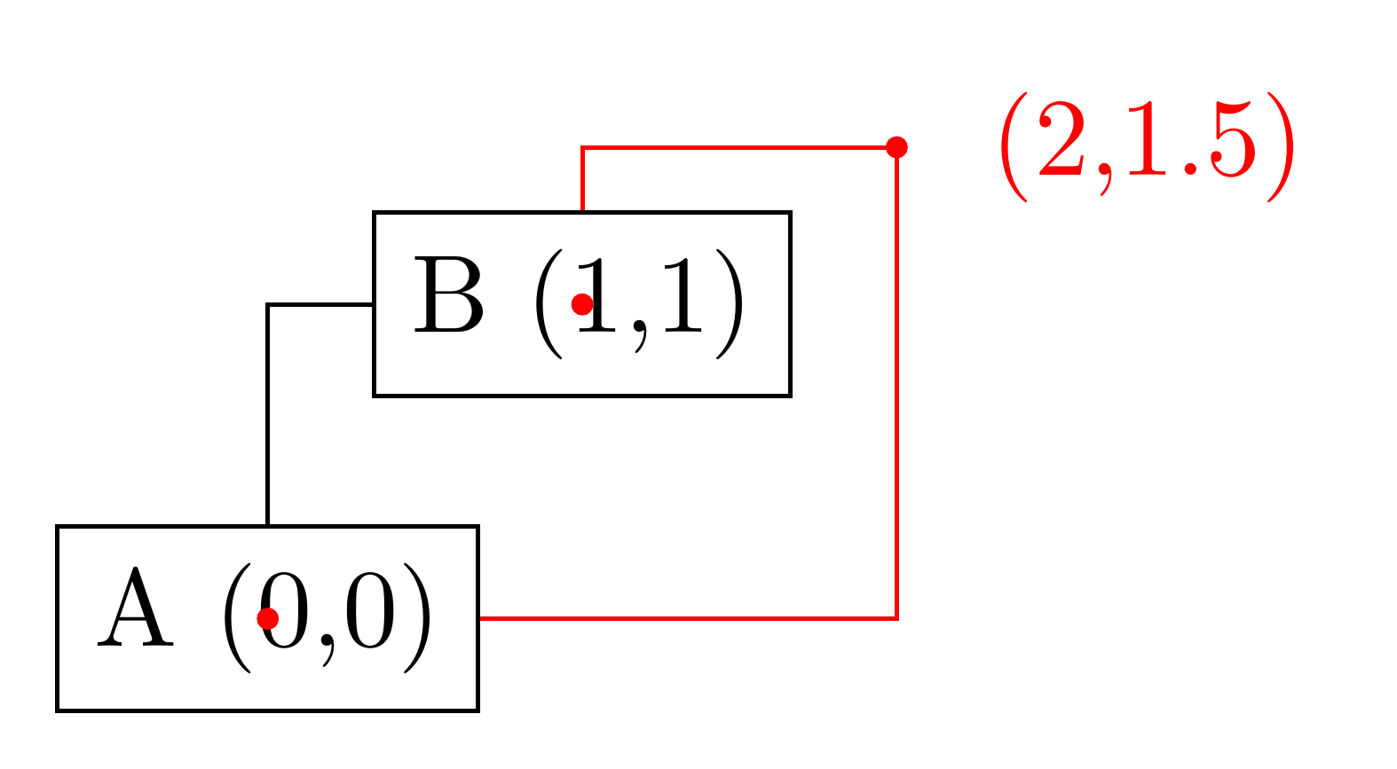
Sometimes you want to connect two points via straight lines that are only horizontal and vertical. For this, you can use two path construction operations.
\path ... -| <coordinate or cycle> ...;: This operation means “first horizontal, then vertical”.
\path ... |- <coordinate or cycle> ...;: This operation means “first vertical, then horizontal”.
…
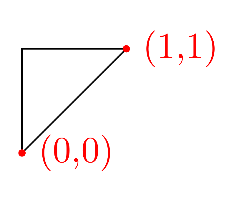
Instead of a coordinate you can also write cycle to close the path.
1
2
3
4
5
6
7
8
9
10
11
12
13
14
15
16
\documentclass{standalone}
\standaloneconfig{border=5pt}

\usepackage{tikz}

\begin{document}
	\begin{tikzpicture}
		\draw (0,0)node(a)[draw]{A (0,0)} (1,1)node(b)[draw]{B (1,1)};
		\fill[color=red] (0,0)circle(1pt);
		\fill[color=red] (1,1)circle(1pt);

		\draw (a.north) |- (b.west);
		\draw[color=red] (a.east) -| (2,1.5)node[anchor=west,right=5pt]{(2,1.5)} -| (b.north);
		\fill[color=red] (2,1.5)circle(1pt);
	\end{tikzpicture}
\end{document}
1
2
3
4
5
6
7
8
9
10
11
\documentclass{standalone}
\standaloneconfig{border=5pt}
\usepackage{tikz}

\begin{document}
	\begin{tikzpicture}
		\draw (0,0)node[red,right=1pt]{(0,0)} -- (1,1)node[red,right=1pt]{(1,1)} -| cycle;
		\fill[color=red] (0,0)circle(1pt);
		\fill[color=red] (1,1)circle(1pt);
	\end{tikzpicture}
\end{document}
13.3.1 Intersections of Perpendicular Lines2
…
Coordinate system perpendicular
…
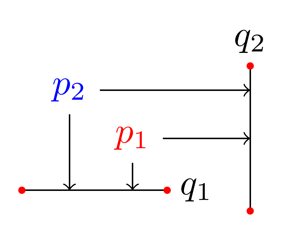
However, in almost all cases you should, instead, use the implicit syntax. Here, you write (<p> |- <q>) or (<q> -| <p>).
For example, (2,1 |- 3,4) and (3,4 -| 2,1) both yield the same as (2,4) (provided the $xy$-coordinate system has not been modified). The most useful application of the syntax is to draw a line up to some point on a vertical or horizontal line.
The most useful application of the syntax is to draw a line up to some point on a vertical or horizontal line [as follows].
1
2
3
4
5
6
7
8
9
10
11
12
13
14
15
16
17
18
19
20
21
22
\documentclass{standalone}
\standaloneconfig{border=5pt}
\usepackage{tikz}

\begin{document}
	\begin{tikzpicture}
		\path (30:1cm)node(p1)[red]{$p_1$} (75:1cm)node(p2)[blue]{$p_2$};

		\draw (-0.2,0) -- (1.2,0) node(xline)[right]{$q_1$};
		\fill[color=red] (-0.2,0) circle (1pt);
		\fill[color=red] (1.2,0) circle (1pt);

		\draw (2,-0.2) -- (2,1.2) node(yline)[above]{$q_2$};
		\fill[color=red] (2,-0.2) circle (1pt);
		\fill[color=red] (2,1.2) circle (1pt);

		\draw[->] (p1) -- (p1 |- xline);
		\draw[->] (p2) -- (p2 |- xline);
		\draw[->] (p1) -- (p1 -| yline);
		\draw[->] (p2) -- (p2 -| yline);
	\end{tikzpicture}
\end{document}
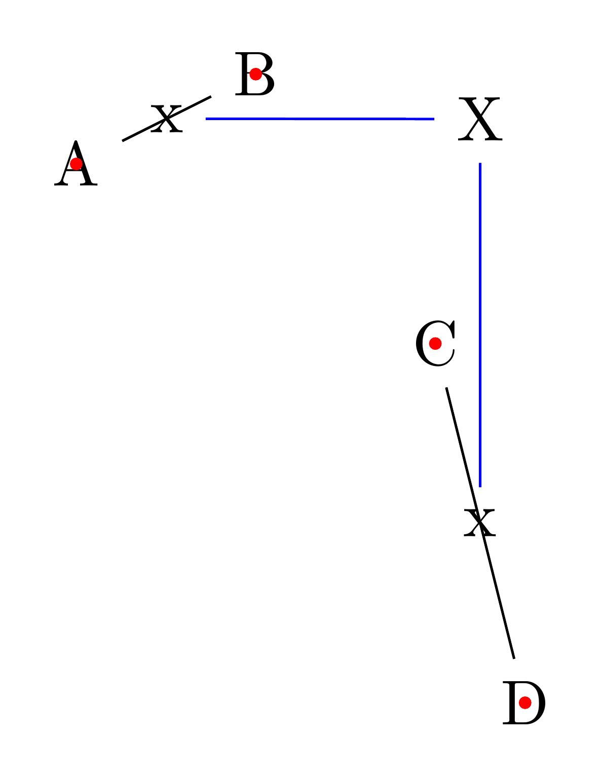
Note that in (<c> |- <d>) the coordinates <c> and <d> are not surrounded by parentheses. If they need to be complicated expressions (like a computation using the $-syntax), you must surround them with braces; parentheses will then be added around them.
1
2
3
4
5
6
7
8
9
10
11
12
13
14
15
16
17
18
19
20
21
22
23
24
25
26
27
\documentclass{standalone}
\standaloneconfig{border=5pt}

\usepackage{tikz}
\usetikzlibrary{calc} % necessary

\begin{document}
	\begin{tikzpicture}
		\node (A) at (0,1){A};
		\fill[color=red] (0,1)circle(1pt);

		\node (B) at (1,1.5){B};
		\fill[color=red] (1,1.5)circle(1pt);

		\node (C) at (2,0){C};
		\fill[color=red] (2,0)circle(1pt);

		\node (D) at (2.5,-2){D};
		\fill[color=red] (2.5,-2)circle(1pt);

		\draw (A) -- (B) node(ABx)[midway]{x};
		\draw (C) -- (D) node(CDx)[midway]{x};

		\node(X) at ({$(A)!.5!(B)$} -| {$(C)!.5!(D)$}) {X};
		\draw[blue] (ABx) -- (X) -- (CDx);
	\end{tikzpicture}
\end{document}
References
-
pgfmanual.pdf, pp. 156. ˄
-
pgfmanual.pdf, pp. 144. ˄