The Example "Diagrams as Simple Graphs" from LaTeX TikZ Documentation
Sep. 24, 2023 • Updated Jun. 08, 2025
1
2
3
4
5
6
7
8
9
10
11
12
13
14
15
16
17
18
19
20
21
22
23
24
25
26
27
28
29
30
31
32
33
34
35
36
37
38
39
40
41
42
43
44
45
46
47
48
49
50
51
52
53
54
55
56
57
58
59
60
61
62
63
64
65
\documentclass[border=20pt,tikz]{standalone}
\usepackage{xcolor}
\usepackage{tikz}
\usetikzlibrary{shapes.misc,graphs,arrows.meta}
\begin{document}
\begin{tikzpicture}
[ % The graphic options are specified in key lists. All graphic options are local to the `{tikzpicture}` to which they apply.
>={Stealth[round]}, % Arrow style; `>` stands for the end of the arrow, equal to `<->/.tip`
black!50, % Arrow color
text=black, % Text color
thick, % Arrow weight
every new ->/.style = {shorten >=1pt},
% `every new ->` means that "whenever encountering ->"
% `shorten >=1pt` means that "shorten the path by 1pt in the direction of the end point."
% Note that there should be one or more space after the `shorten` key, otherwise an error will occur
graphs/every graph/.style = {edges=rounded corners},
% Specify all edges in the graph, i.e., connections between nodes, be drawn with rounded corners
% `graphs` is a TikZ package
skip loop/.style = {to path = {-- ++(0,#1) -| (\tikztotarget)}}, % Define a new style called `skip loop`
hv path/.style = {to path = {-| (\tikztotarget)}}, % Define a new style called `hv path`
vh path/.style = {to path = {|- (\tikztotarget)}}, % Define a new style called `vh path`
nonterminal/.style = { % Define a new style called `nonterminal`
rectangle,
minimum size = 6mm,
very thick,
draw = red!50!black!50,
top color = white,
bottom color = red!50!black!20,
font = \itshape,
text height = 1.5ex,
text depth = .25ex},
terminal/.style = { % Define a new style called `terminal`
rounded rectangle,
minimum size = 6mm,
very thick,
draw=black!50,
top color = white,
bottom color = black!20,
font = \ttfamily,
text height = 1.5ex,
text depth = .25ex},
shape = coordinate % Comment this line to see the "name" of p1, p2, p3 etc.
]
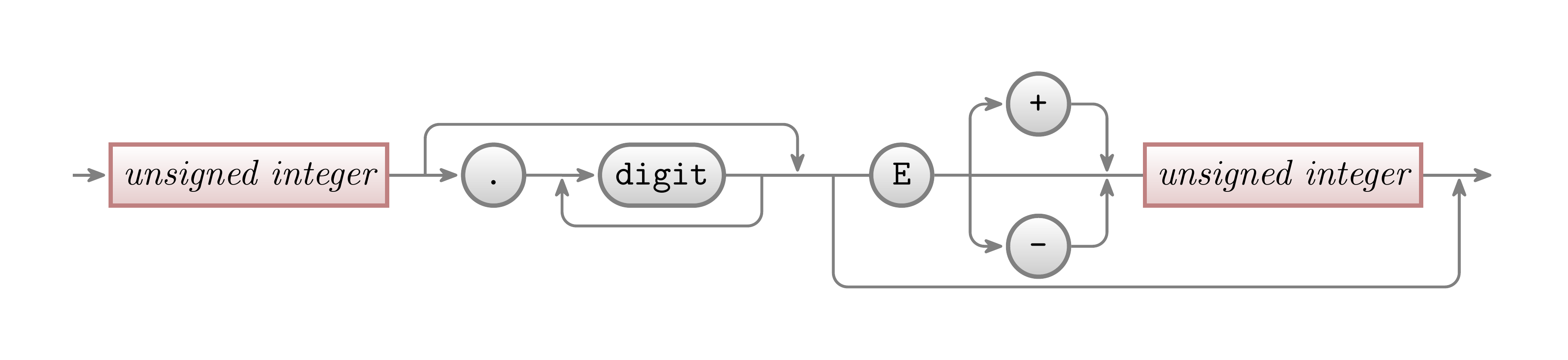
\graph [grow right sep, branch down=7mm, simple]
{
/ -> unsigned integer [nonterminal] -- p1 -> "." [terminal] -- p2 -> digit [terminal] -- p3 -- p4 -- p5 -- E [terminal] -- q1 ->
[vh path] {[nodes = {yshift=7mm}] "+" [terminal], q2, "-" [terminal]} ->
[hv path] q3 -- ui2/unsigned integer [nonterminal] -- p6 -> /;
% Because "unsigned integer" is node content and simultaneously node name and we use it twice,
% we should assign a new node name for the second one, i.e., "ui2" in "ui2/unsigned integer", to make a distinction.
% On the other hand, due to that we won't use this node name later, we can write nothing before /, i.e., `/unsigned integer`,
% which stands for a "fresh, anonymous" node name.
p1 -> [skip loop = 5mm] p4;
p3 -> [skip loop = -5mm] p2;
p5 -> [skip loop = -11mm] p6;
q1 -- q2 -- q3;
};
\end{tikzpicture}
\end{document}
1
2
3
4
5
6
7
8
9
10
11
12
13
14
15
16
17
18
19
20
21
22
23
24
25
26
27
28
29
30
31
32
33
34
35
36
37
38
39
40
41
42
43
44
45
46
47
48
49
50
51
52
53
54
55
56
57
58
59
60
61
62
63
64
65
66
67
68
69
70
71
72
73
74
75
\documentclass[border=20pt,tikz]{standalone}
\usepackage{xcolor}
\usepackage{tikz}
\usetikzlibrary{graphs,arrows.meta}
\begin{document}
\begin{tikzpicture}
[
>={Stealth[round]},
thick,black!50,
text=black,
every new ->/.style = {shorten >=1pt},
graphs/every graph/.style = {edges=rounded corners},
node distance = 5mm and 5mm,
text height = 1.5ex,
text depth = .25ex,
nonterminal/.style = { % Define a new style called `nonterminal`
rectangle,
minimum size = 6mm,
very thick,
draw = red!50!black!50,
top color = white,
bottom color = red!50!black!20,
font=\itshape},
terminal/.style = { % Define a new style called `terminal`
rectangle,
minimum size = 6mm,
very thick,
draw = black!50,
top color = white,
bottom color=black!20,
font=\ttfamily,
rounded corners = 3mm},
point/.style = { % Define a new style called `point`
coordinate,
% circle,
% inner sep = 0pt,
% minimum size = 1pt,
% fill = red
},
skip loop/.style = {to path={-- ++(0,#1) -| (\tikztotarget)}}, % Define a new style called `skip loop`
hv path/.style = {to path = {-| (\tikztotarget)}}, % Define a new style called `hv path`
vh path/.style = {to path = {|- (\tikztotarget)}} % Define a new style called `vh path`
]
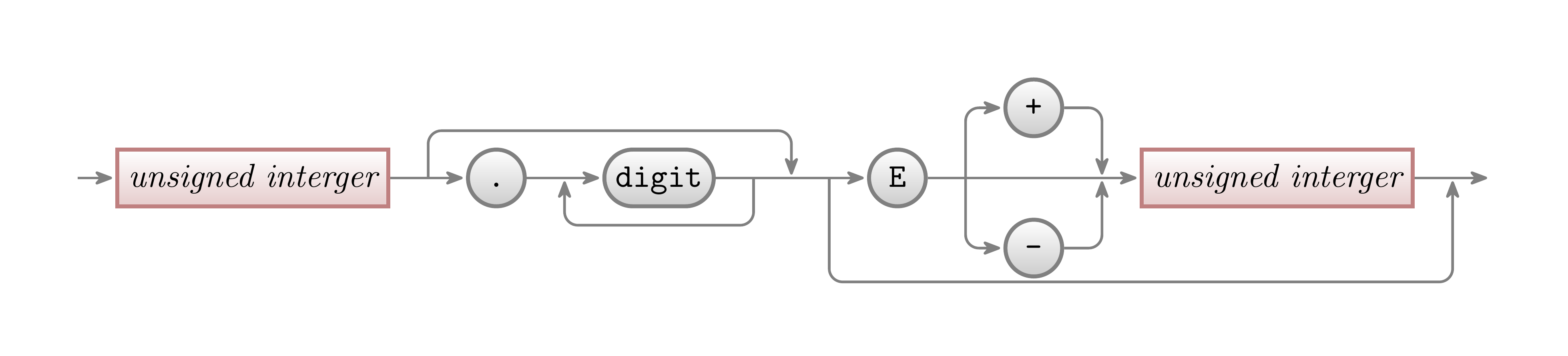
% Use TikZ matrix to align quite arbitrary graphical objects in rows and columns
\matrix[row sep = 1mm, column sep = 4mm]{
% First row:
& & & & & & & & & & & (plus) \node (plus) [terminal] {+};\\
% Second row:
\node (p1) [point] {}; & \node (ui1) [nonterminal] {unsigned interger}; &
\node (p2) [point] {}; & \node (dot) [terminal] {.}; &
\node (p3) [point] {}; & \node (digit) [terminal] {digit}; &
\node (p4) [point] {}; & \node (p5) [point] {}; &
\node (p6) [point] {}; & \node (e) [terminal] {E}; &
\node (p7) [point] {}; & &
\node (p8) [point] {}; & \node (ui2) [nonterminal] {unsigned interger}; &
\node (p9) [point] {}; & \node (p10) [point] {};\\
% Third row:
& & & & & & & & & & & \node (minus) [terminal] {-};\\
};
\graph[use existing nodes] {
(p1) -> (ui1) -- (p2) -> (dot) -- (p3) -> (digit) -- (p4)
-- (p5) -- (p6) -> (e) -- (p7) -- (p8) -> (ui2) -- (p9) -> (p10);
(p4) -> [skip loop = -5mm] (p3);
(p2) -> [skip loop = 5mm] (p5);
(p6) -> [skip loop = -11mm] (p9);
(p7) -> [vh path] (plus) -> [hv path] (p8);
(p7) -> [vh path] (minus) -> [hv path] (p8);
};
\end{tikzpicture}
\end{document}
References
- TikZ & PGF, pp. 70-79.